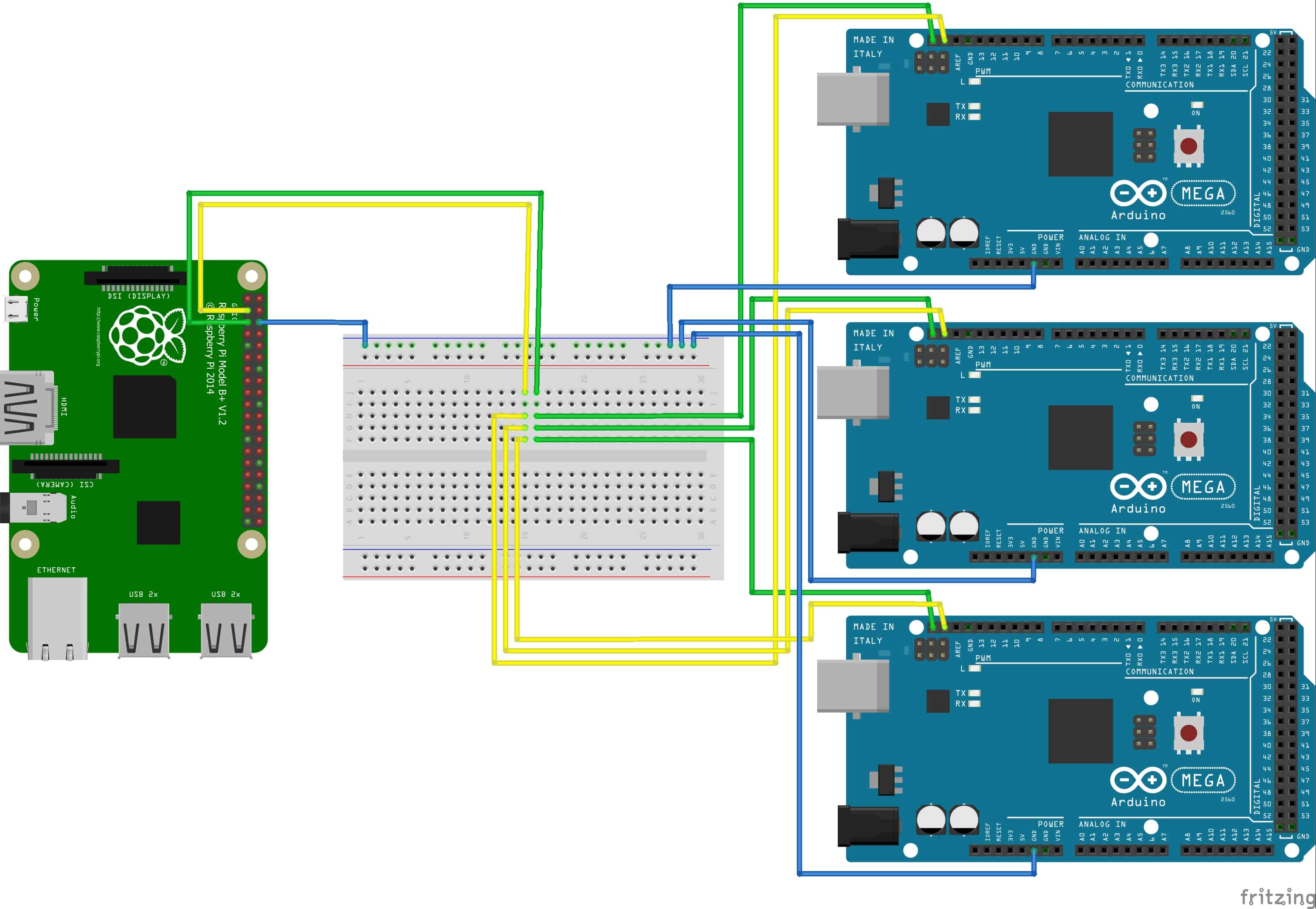

However, you need to be careful when doing this. In this configuration, it is possible to connect the Raspberry Pi and Arduino directly together, as the Master is determining the logic levels. The most common scenario for interfacing a Raspberry Pi with an Arduino is to have the Raspberry Pi assume the role of Master. This type of gate is often used to “clean up” a noisy logic line and will not be triggered by a 3.3-volt signal. This is because most 5-volt logic chips have a threshold of a bit less than 3-volts, in other words, a logic signal of 3-volts or more will be recognized as a valid signal.Īn exception to this is a Schmitt Trigger, a logic gate that has very narrow thresholds for zero and one. Interestingly, a 3.3-volt logic signal is capable of working properly when connected to a5-volt input. You may NOT connect a 5-volt output to a 3.3-volt input.You may connect a 3.3-volt output to a 5-volt input.The rule for connecting the two logic families together is pretty simple: The original microprocessors of the 1970s used this type of logic, as did the discrete CPU designs before them.ĭespite its age 5-volt logic is still very common, and it’s no coincidence that the standard USB voltage is 5-volts (although the newer USB-C can make use of multiple voltages).ģ.3-volt logic devices have also been around for many years, they are popular as they consume less current and are therefore ideal for battery-powered devices. Mixing Logic Levelsĥ-volt logic, also sometimes referred to as “TTL logic”, has been around for many decades. Keep that in mind when we start hooking up our Raspberry Pi and Arduino. This concept is very important to understand when interfacing devices with mixed logic levels.Īnother important concept is that it is the Master that determines the logic voltage level. These resistors pull the logic and clock levels up to the level of the VCC reference voltage. The arrangement of master and slaves(s) is illustrated below. In many arrangements, this voltage is also used to power the slave device. VCC – This is the logic-level voltage reference, typically either 5-volts or 3.3.-volts.This provides the clock signal to synchronize the data on the SDA line. This is a bidirectional data line, handling all communications between the master and slave(s). An I2C circuit consists of one bus “Master” and one or more bus “Slaves”.
#PI ARDUINO I2C EXAMPLE TWO WAY DATA COMMUNICATION SERIAL#
I2C operationĪs a quick recap I2C, or the ”Inter-Integrated Circuit Bus”, is a method of exchanging serial data between two or more devices. If you just need a quick refresher then please read on. If you need a detailed explanation about the I2C bus please see the first article in this series. I2C Voltage Levelsīefore we examine the issues with mixing multiple I2C devices of different logic-levels it would be a good idea to make sure that we are familiar with the i2c bus and how it operates.

In fact, there are two ways to do it.įollow along and we’ll examine both ways of interfacing a Raspberry Pi and an Arduino using the I2C bus.

However, despite these voltage differences it is possible to interface the two devices. The Raspberry Pi uses 3.3-volt logic, whereas most Arduino’s (including the Arduino Uno) make use of 5-volt logic. Both the Arduino and the Raspberry Pi support I2C, however interfacing them can present a special challenge as they don’t work at the same logic voltage levels.


 0 kommentar(er)
